Design &
Engineering
From an idea, through the prototype, to serial production.
The goal of the Design & Engineering team is to transform an idea into the final product. AIC uses computer-aided design software (CAD), rapid prototyping and simulations to create accurate, reliable and efficient designs.
Overview
Our R&D and Industrialization Engineering teams explore ideas adjusted to the clients’ preferences, provide thermal efficiency tests, material analysis, identify processes and technologies that could be used to create new or improved products.
Our design & engineering process is divided into several phases. During the first stage, we introduce the initial parameters of a new product, which are then verified in thermal calculations. The first validation of the proposed heat exchanger design is made during FEA (Finite Element Analysis). This approach saves time compared to validation based on physical unit testing. The FEA department combines FEM (Finite Element Method) and CFD (Computational Fluid Dynamics) experts that use Ansys Workbench for numerical simulation of mechanics, thermal flow, combustion and scaling. The next step is constructing a physical unit by prototyping cell and testing it in thermal laboratory. Once the tests’ numerical and physical results confirm that the product is valid, the next phase of the project can be initiated.
The industrialization stage is focused on adapting prototype design documentation to manufacturing capabilities and required standards.
We design according to the American Society of Mechanical Engineers (ASME) Code. It applies to boilers, pressure vessels, and other related equipment design and construction. We also design products according to the PED Directive and SELO requirements.
Project Stages
AIC specializes in developing a wide variety of heat exchangers. With residential and commercial boilers, water heaters, economizers, pool heaters, and individual units dedicated to chemical, food, oil & gas industries – we deliver versatile and thoroughly tested solutions.
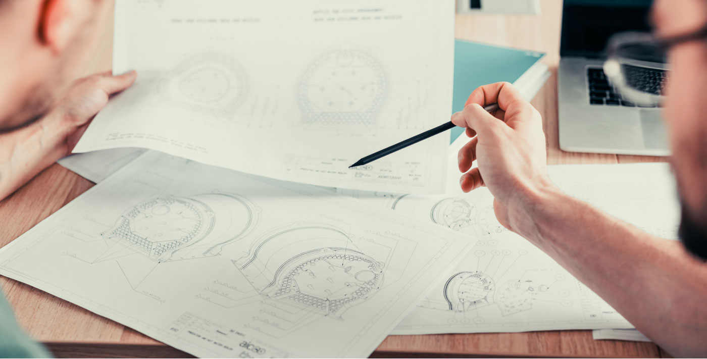
Concept
At the beginning of the concept phase, we gather all accessible data: working parameters, client needs, and other technical and market requirements. Then, preliminary thermal calculations are made, and several initial solutions are proposed for further consideration. Each design must meet the critical conditions of a project (i.e. efficiency, power, and geometry limitations). The concept stage ends with selecting the most preferable solution.

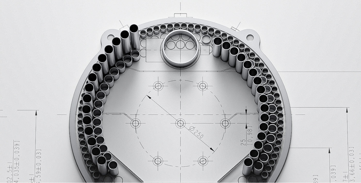
Design & Development
We prepare prototype documentation (3D models and drawings) at the design development stage. During this phase, we discuss proposed designs with the client and adjust them for additional or new requirements. Depending on the client’s needs, we select and modify heat exchangers from our portfolio or design entirely new ones.
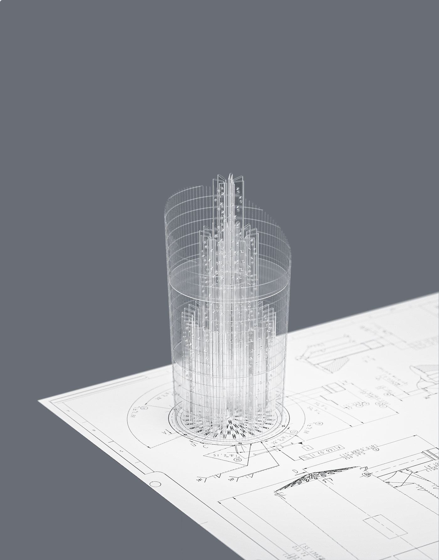
CFD/FEM Analisys
Numerical analyses verify the chosen design. Thermal and flow calculations are our specialists' most common CFD analyses.
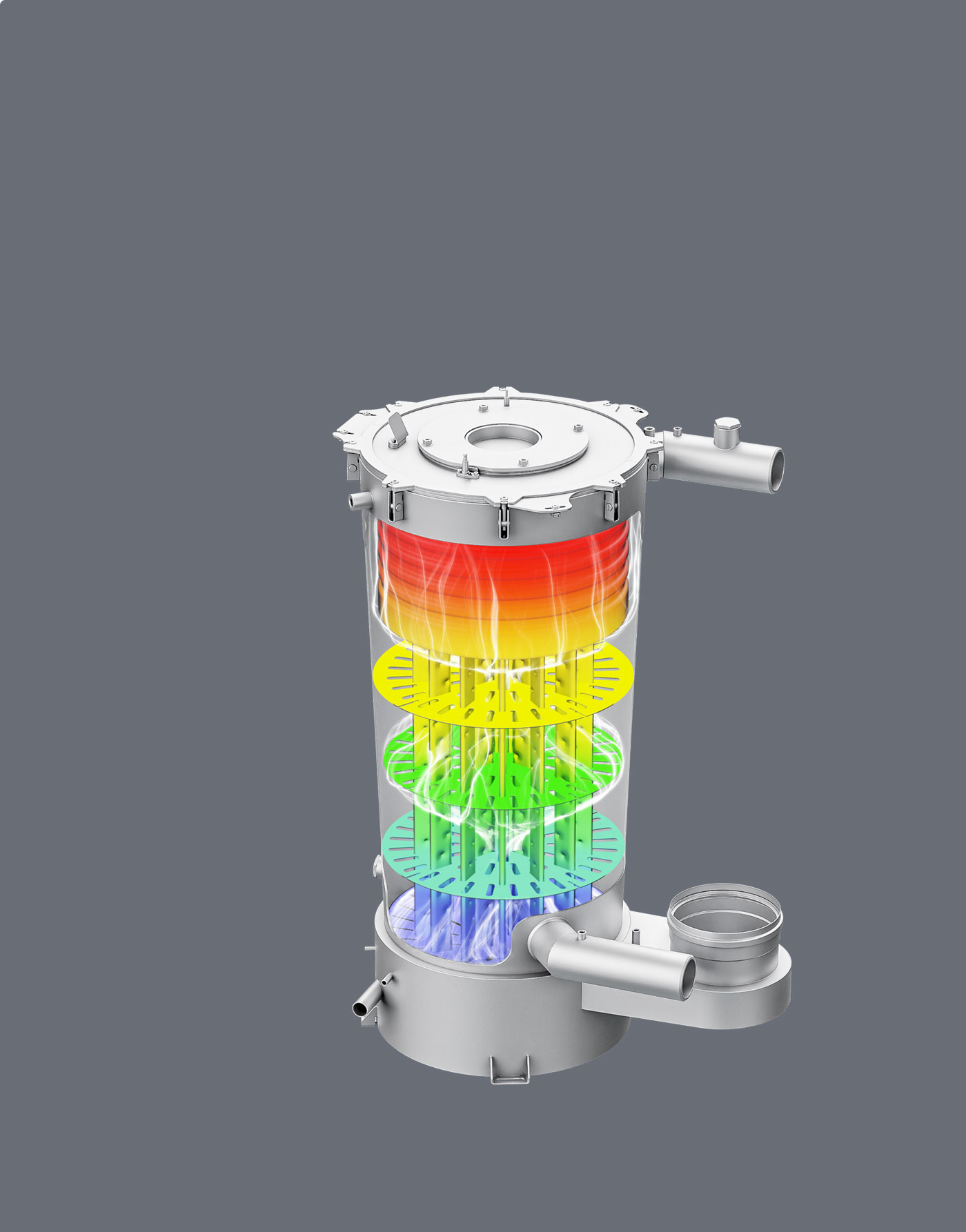
Thanks to these simulations, we can see how fluids and gases are distributed inside our heat exchangers. This verification shows how a unit works and whether there is any area that needs improvement. Optimization by CFD analysis is a powerful method that saves time and resources. Our CFD experts can also conduct electrochemical simulations (combustion, condensation, and scaling).
Once all needed CFD calculations are finalized, a 3D model of a heat exchanger is validated by the FEM team, and then structural analyses start. During this phase, different types of loads can be applied to a numerical model (force, pressure, temperature, acceleration, and cycling loads). Design is accepted when stress and deformation levels are below desired limitations. The FEA team performs static and dynamic analyses. Our CFD and FEA experts can run calculations on two servers, each consisting of 8 nodes with 64 cores.
Prototype and Laboratory Tests
We have the best welders in the AIC protoshop cell. Thanks to their experience and mastery abilities, even the most complex designs can be manufactured within a short timeframe. The units built in the prototype workshop are tested in the laboratory for verification.
In the thermal laboratory, we perform:
Thermal efficiency and working parameters test
One station for units up to 250 kW, a second station for units up to 2 MW.
Life test (six stations)
We simulate the cyclical work of a heat exchanger similar to the typical use of the end user (at nominal parameters).
Fatigue test (hammer test)
A unit is pressurized thousands of times for endurance verification.
- Calcification (scaling) test
- Noise level test
- IR emission
- Pressure drops for the gas side and head losses for the waterside
- Thermal losses on standby status
- NOx classification
- Boiling parameters
- Temperatures on a different internal surface of a heat exchanger (combustion chambers, top tubesheet, fire tubes)
If the results align with the initial assumptions, prototypes are ready for testing on the customer's side. AIC also has a material laboratory and a separate lab for hydrogen applications. We are working on future technologies for the demanding heat transfer market in these two laboratories.
Final product design
AIC and the client can approve the prototype once all tests are completed. Then, it is time for the industrialization team to start working on the production documentation according to the selected standards: ASME, CRN, PED, and SELO. The GD&T tolerancing system is used to provide the correct geometry of our products. During the implementation of the serial production process, the final design is validated by manufacturing several product samples with tooling and jigs.
Stage 1.
Concept
At the beginning of the concept phase, we gather all accessible data: working parameters, client needs, and other technical and market requirements. Then, preliminary thermal calculations are made, and several initial solutions are proposed for further consideration. Each design must meet the critical conditions of a project (i.e. efficiency, power, and geometry limitations). The concept stage ends with selecting the most preferable solution.
Stage 2.
Design & Development
We prepare prototype documentation (3D models and drawings) at the design development stage. During this phase, we discuss proposed designs with the client and adjust them for additional or new requirements. Depending on the client’s needs, we select and modify heat exchangers from our portfolio or design entirely new ones.
Stage 3.
CFD/FEM Analisys
Numerical analyses verify the chosen design. Thermal and flow calculations are our specialists' most common CFD analyses.
Thanks to these simulations, we can see how fluids and gases are distributed inside our heat exchangers. This verification shows how a unit works and whether there is any area that needs improvement. Optimization by CFD analysis is a powerful method that saves time and resources. Our CFD experts can also conduct electrochemical simulations (combustion, condensation, and scaling).
Once all needed CFD calculations are finalized, a 3D model of a heat exchanger is validated by the FEM team, and then structural analyses start. During this phase, different types of loads can be applied to a numerical model (force, pressure, temperature, acceleration, and cycling loads). Design is accepted when stress and deformation levels are below desired limitations. The FEA team performs static and dynamic analyses. Our CFD and FEA experts can run calculations on two servers, each consisting of 8 nodes with 64 cores.
Stage 4.
Prototype and Laboratory Tests
We have the best welders in the AIC protoshop cell. Thanks to their experience and mastery abilities, even the most complex designs can be manufactured within a short schedule. The units built in the prototype workshop are tested in the laboratory for verification.
In the thermal laboratory, we perform:
Thermal efficiency and working parameters test
One station for units up to 250 kW, a second station for units up to 2 MW.
Life test (six stations)
We simulate the cyclical work of a heat exchanger similar to the typical use of the end user (at nominal parameters).
Fatigue test (hammer test)
A unit is pressurized thousands of times for endurance verification.
- Calcification (scaling) test
- Noise level test
- IR emission
- Pressure drops for the gas side and head losses for the waterside
- Thermal losses on standby status
- NOx classification
- Boiling parameters
- Temperatures on a different internal surface of a heat exchanger (combustion chambers, top tubesheet, fire tubes)
If the results align with the initial assumptions, prototypes are ready for testing on the customer's side. AIC also has a material laboratory and a separate lab for hydrogen applications. We are working on future technologies for the demanding heat transfer market in these two laboratories.
Stage 5.
Final product design
AIC and the client can approve the prototype once all tests are completed. Then, it is time for the industrialization team to start working on the production documentation according to the selected standards: ASME, CRN, PED, and SELO. The GD&T tolerancing system is used to provide the correct geometry of our products. During the implementation of the serial production process, the final design is validated by manufacturing several product samples with tooling and jigs.